
Racing Inter Update-Post Cadwell (Winter 2012/3)
Progress on 38 Norton Racing Inter:- One Step Forward, Two Steps Back
You may remember an update I gave back in October 2012, detailing my tail of woes after a particularly unsuccessful race meeting at Cadwell, resulting in cracked crankcases and a failed BTH magneto on my 38 Racing International (as detailed in the first article on my Blog page).Well since that date I have been slowly but diligently working to repair the damage and get the bike back together - particularly as I need it back and operational so I can test a new batch of parts just being manufactured. Unfortunately it has been fighting me all the way and has not been an easy process at all (hampered more so by recent family illness, making my time even more limited than usual), but progress is now finally being made.
I had taken the crankcases for welding to my old friend Arthur Sosbe, who has now all but retired. I decided to 'sacrifice' the drive side main bearings to the welding process, by keeping them in and fitting a large steel mandrel in the assembled crankcases - so that the outside of the crankcases could be welded with the mandrel in-situ, the hope being that the distortion would be minimised and the crankcases would still be usable without further machining. Arthur is well known in Leicester and the finest welder I know, but even he was worried this might not be enough . . . but offered to give it his best shot. I had to wait a few weeks, as Arthur has now pretty much handed his main commercial business over to one of his team, but still does the occasional job like this if I do not mind waiting. So just before Xmas I got a call to say the crankcases were ready to collect. I have to say, considering the amount of welding that had to be carried out, the external finish of the crankcases did not look half as bad as I thought they would, Arthur had done a very nice job keeping the crankcases looking as per original, and had even done a little bit of post weld fettling around the webs afterwards.
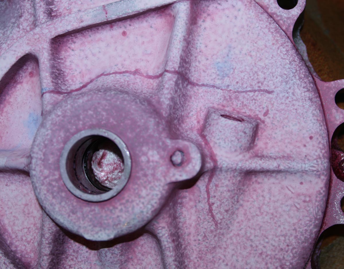
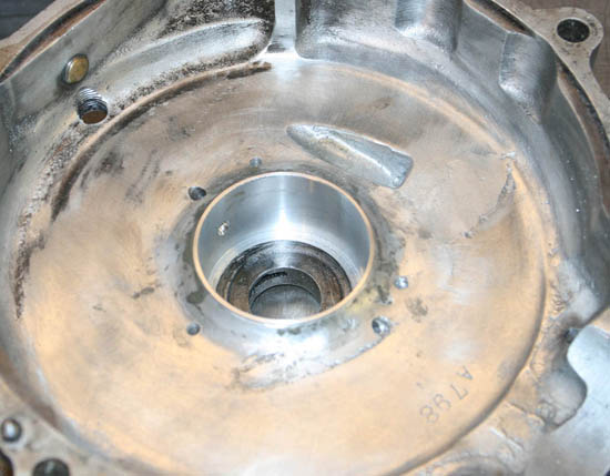
Crankcases as they looked following the October 2012 Cadwell BHR meeting - Dye Penetrant shows cracks across the webbing - not good
Consequences of Welding
However, he did tell me he had noticed while welding that the aluminium was showing its age and did not weld as well as a more modern alloy - so we will just have to see how well it holds up in use. As expected there was some slight visible distortion as I unbolted the crankcases, you could see that one side of the barrel mouth between the crankcases now had a couple of thou gap - something I have seen before when welding Norton single cylinder crankcases up. Arthur had told me beforehand the bearings would almost certainly be damaged by the amount of heat that would be required to weld them up. I had quietly been more optimistic, particularly as the crack did not run right through the bearing housing, it being just above. But it became immediately clear on splitting the crankcases that he was right and I was wrong - the drive side bearings were well buggered! - Completely fried. First of all the Castor oil that the bearings were running in was virtually black and had turned to an araldite like substance - I could not even move the bearing races. But even allowing that, once I heated the crankcases and got them out it was clear they were completely useless, with even the rollers blued.
No worries, I had figured the main bearings would get replaced anyway . . . so this made the decision a no-brainer. However, next issue was that before heating the crankcases up to accept the new bearings, I thought I would gently try one in cold - and unfortunately it started to slide in - bugger again! There is normally no way a bearing should go in cold . . . that normally means it will spin in the housing once in use. But it is not an uncommon problem on Norton cammy crankcases, particularly if a bearing has started to creep over the years in use (normally identifiable by a matt grey finish on the crankcase bearing wall, or even worse – scoring) - and if not too bad, can just about be got away with by using (Loctite) Bearing Fit. So I heated the crankcases up anyway, coated the outer tracks of both new drive side bearings in Bearing Fit and dropped them in. With hindsight heating the crankcases up first was not a good idea . . . and this I would pass on as a hint for anyone reading this - if you have to use Bearing Fit, it is better to use it 'cold' because the heat seems to cure the liquid very quickly indeed, not allowing the bearing to slide. In this case the ball bearing locked up before fully hitting the bottom of the journal. I eventually got it in, but was not entirely happy - talking with Stu Rogers afterwards, his view confirmed this - that if you fit it into a hot crankcase, it 'cures' the Bearing Fit too fast, therefore cold is better.
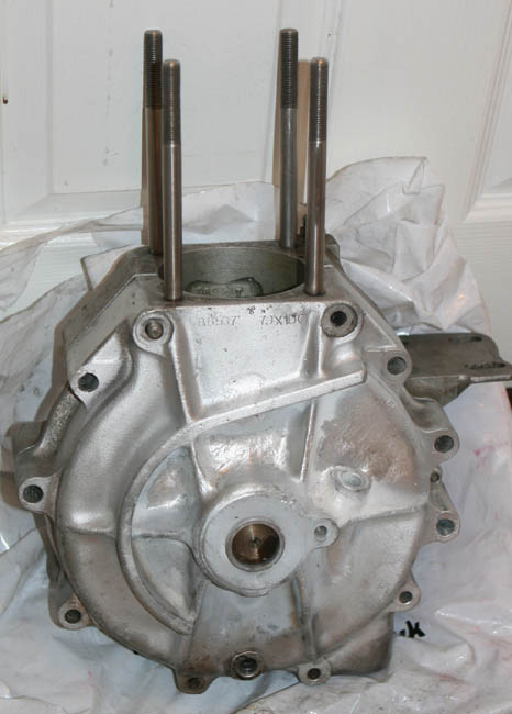
And this is how they looked after comprehensive welding by Arthur Sosbe. You have to get quite close before it becomes obvious
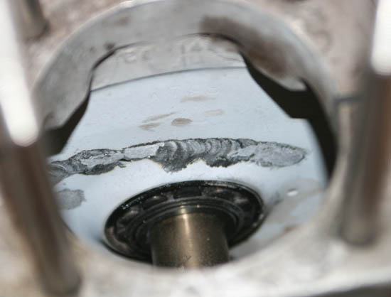
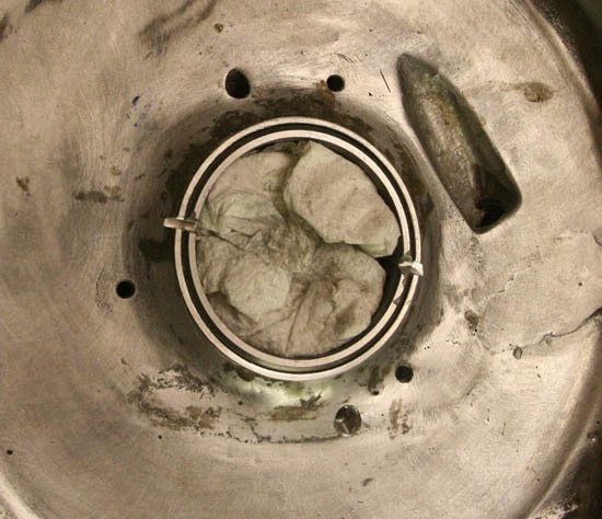
And here they are looking inside from the base of the barrel. Here you can just see the steel mandrel going into the bearings - both looking fried
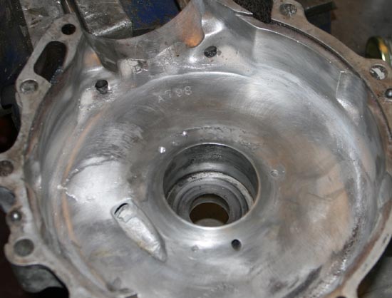
And here is the inside of the crankcases after gentle cleaning up. The weld starts at the top left above the breather and continues over to the right above the mains housing as well as vertically down through the breather itself. At this stage the mains housing is original
All Is Not Well . . .
Anyway, with bearings fitted I could not put it off any longer, so did a trial crankshaft assembly - not bothering with any shims, or bearing cover plate fitted - just to see if the crankshaft would spin ok. I fitted the crankshaft in the timing crankcase first, then placed the drive side crankcase over the drive mainshaft and started to tap it down, but as the two crankcase half's came close to being fully mated I could tell things were not looking promising - the front area of the crankcases half's had started to touch, but the rear of the crankcases still had a couple of thou (thousandths of an inch) to go. I then went round the crankcase fitting engine bolts and slowly tightening them up. At first the crankshaft was turning relatively freely, but as I got to the last 'half a turn' all of a sudden things started to go tight - to the extent that although with some effort I could just about revolve the crankshaft, but under no circumstances would there have been any point trying to run the engine in this state - even if it had ran, half the horsepower would have been used up just getting it to tick over!At this point I removed the bearings (far more difficult than you might think - Bearing Fit does it's job well!), cleaned off all the Bearing Fit and fitted them again 'dry', just to make sure, but it was no good - despite all best efforts the distortion had proven too much and more radical surgery would be necessary.
Sleeving and Jig Boring
Although hoping to avoid the much bigger job of boring out the main bearing housing and fitting a sleeve, it was now obvious this would be necessary, but luckily my old friend Rob (who I am now also working very closely with to manufacture the SOHC Magnesium crankcases) was at hand and very kindly agreed to take on the job - I know my own machining limitations, and although I might just about have managed to bore out the drive side bearing crankcase and fit a sleeve - there is no way with my limited machinery I would have been able to 'jig bore' the new housing, as this would need to be done in line with the timing crankcase bearing, with both crankcase half's assembled. About two weeks later Rob called me to say the crankcases were ready, and I duly collected them. Rob had done a great job and the new sleeve looked really good. Rob mentioned that he had used a piece of aircraft quality aluminium stock that he had, and had actually used liquid Nitrogen to shrink it in - it certainly looks a much better quality than the old Norton alloy, so might restore a bit more strength around the bearing housing.This time when fitting the drive side main bearings I did have to heat the crankcases up to drop the bearings in and the interference fit felt just about perfect. As you see with a number of racing Norton's though, I also carefully ground a notch in the outer race of the roller bearing, so that a similar notch in the outer bearing plate can be used to stop the bearing rotating.
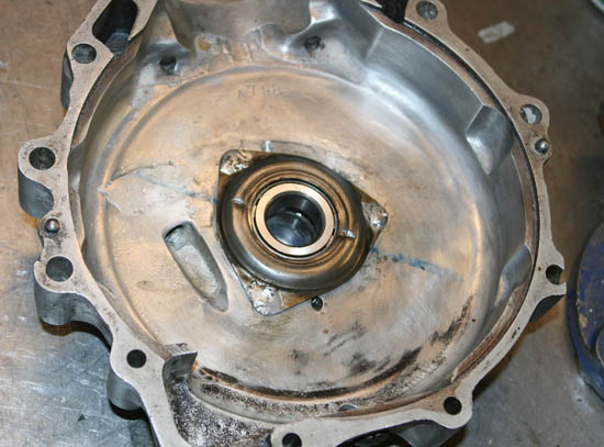
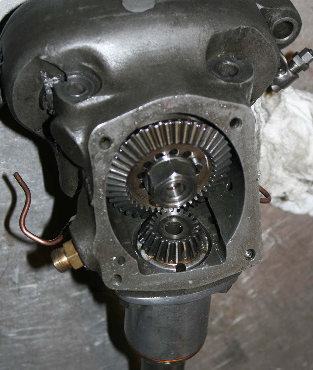
And the same Mains housing again, after the fitting of a sleeve and jig boring to get it back true and in line with the other crankcase beaaring journal - not a task you want to take on unless you really have to!
Here you can see the new roller bearing outer race fitted, and very carefully a slot has been ground in both the race and housing
And finally, with bearing cover fitted and corresponding marks punched into the cover. Note the blue highlight marker to remind me where the slots were made!
Re-Assembly and Further Woes
So again I found myself assembling the crank into the crankcases, minus shims and bearing covers, with a certain amount of trepidation. I have to say though that this time I was a little more confident, and with good reason; Although getting the crankcase half’s to join up at all was a bit of a bind, because of the tight fit of the inner races on the drive side mainshaft (which at first was disconcerting until I realised what the problem was), once the crankcase half’s were together and bolted up they felt much better than they had first time round. I had a few worrying seconds when I first spun the crank, as I felt a slight resistance at first – probably the bearings and spacers sorting themselves out, then it went round relatively smoothly with no noticeable tight spots. Not quite as free as the old crank – but then again I would not expect it to be, these are brand new bearings in a thick coating of very cold castor oil (remembering it is the middle of winter and I do not have heating in my workshop!). So this was good news and it was at this point that I realised that I may have got lucky and have been able to ‘save’ these crankcases, or at least got them to a good enough state to be worth carrying on with the assembly.
So I stripped the engine down again one more time and went through all the normal bottom end assembly tasks – fitting bearing plates (and adding indents in line with the bearing grooves, to help stop future rotation), shimming to get conrod central, bottom bevel fitting etc and then final assembly. On spinning the crank after final assembly I had a brief scare when I felt slight resistance and scraping – until I realised it was the crankpin just touching the excess soft solder on the bearing plate, other than that things went ok and it was not long before I had the bottom half assembled and barrel and head back together.
Magneto Fix
If you read my original Cadwell blog last autumn you might remember the actual problem that put me out of the race at Cadwell was not the crankcases (although undoubtedly the state of the drive side crankcase would have put me out of the race in a big way had I continued!), but it was in fact the BTH magneto that had failed. On inspection I found it was a very obscure issue – the thread in the end of the armature that retained the points plate had failed and the points plate had come loose – therefore loss of spark.So, with the engine assembled, this was the next job and not one I had ever tackled before, being quite an unusual issue. I checked the original brass thread in the armature and could see that though there looked to be a little of it left, it was not enough to hold the points ring securely. Initially I considered helicoiling, but was not sure if that would affect the conductivity – and how easy it would be to find a helicoil that small anyway! I then thought about opening it out and fitting a brass insert, then re-tapping. But in the end I did the simplest thing I could first, which was to just re-thread the hole of the armature to the next thread size up from its current thread. This thread (if I remember correctly) was 1BA. I drilled out to the correct tapping size (noticing that there was not actually very much depth of brass before I hit the fibrous non-conductive material.
Re-tapping the armature was actually the simple bit, the next step was making a new central bolt. The original BTH bolt is very distinctive with a tapered shoulder to centralise the points plate and a domed head to provide a ‘touch point’ for those that wanted to fit a ‘dead stop’ electrical cutoff, which I was not worried about. I wanted my replacement to have the same approximate dimensions, but obviously with a larger diameter. Eventually, instead of making one from scratch I was able to adapt an existing 1BA bolt and reduce its shaft diameter where it fed through the points plate, to reduce the chance of it ‘shorting’ against the bore of the points plate. I also had to drill out the centre of the points plate fractionally, to allow the threaded part to pass through. At this point I found a feature that I had not accounted for – as I started to drill something was spinning but the drill was not going through. It turns out the points plate has a fibre bush fitted (not surpisingly I suppose), and trying to drill through this was causing it to spin. Eventually I did get through it and although awkward I was able assemble the plate using the new bolt and make adjustments to the taper I had made on the bolt in the lathe, so it centered nicely. Last task was to fit my little spark testing handle and ensure it still had a spark – which it did, job done! Actually, I was rather pleased with this fix, because I had an idea this might be a difficult one, and could even result in me having to replace the armature, but in the end the fix cost me nothing but a couple of hours time and looks like it will be a good secure fix.
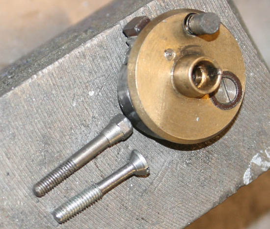
Here you can see the original BTH centre bolt on the left, and new bolt on the right, which has a larger diameter thread, but is reduced around the shaft to avoid shorting on the points plate. You can just see the recess inside the points plate which holds a fibre bush to insulate against the two parts touching
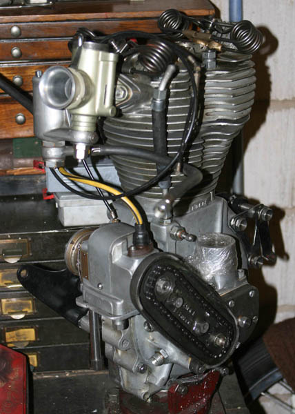
And here is the engine rebuilt on the engine stand with BTH KD1 mageto now refitted and ready to go back in the frame
Post Magneto Re-Assembly . . . Sort Of
With the magneto now sorted and firing, I could get on with re-assembling the engine back in the frame and doing the final assembly. This was all straight forward – if rather laborious and awkward, I have done it many times before, but having only very limited room in my garage (and even less now, with the Vincent twin finally on its own wheels and poking me menacingly in the back!), it is very awkward trying to do the reassembly in the little space I have. I could have course have opened the garage door and moved a couple of bikes out, but feeling still very much like the middle of winter in my unheated garage, I decided I would rather be cramped and bullied by the Vincent, rather than being any closer to hypothermia than I already was!
Anyway, other than the space issue, the reassembly went ok and things were soon back together, to the point where the cambox was ready to go on. The main reason for wanting to get the build done as quickly as possible was that I had just received a new batch of cambox rocker pads and need to test them as quickly as possible, so a pair of these had already been fitted into the rockers and the cambox was reassembled ready to fit.
However, the assembly task was about to take another unpleasant turn – as the next job was to ensure the valve timing was still set correctly. I went through the normal cambox assembly process, knowing it did not matter too much which stroke it was assembled on, as the magneto was still to be timed and the only thing that could change the original valve timing was the lower bevel gears. When I had re-fitted the lower bevel housing in the crankcase, I had been very careful to ensure I got the timing marks set correctly. But as most cammy Norton owners who have done this task will know – there comes a point where you are effectively working blind and you cannot clearly see the marks behind the mainshaft and oil drive gear, which must be fitted first. I thought I had got this right (using my little inspection mirror to help me) . . .but having spent another weekend afternoon session assembling all the top half and then fitting timing disk . . . when I started to measure the valve timing, it was apparent that both inlet and exhaust timing were approx 20 degrees out – bugger! Evidently I had assembled the lower bevel one tooth out of sync, either that or I had originally assembled it one tooth out many years ago – but the upshot was the same, it was late afternoon, I was tired and cold and I was now looking at having to totally remove all the top end again, so I could get to the lower bevel and move the lower vertical bevel to reset the valve timing.
And it was at this point, just when I thought my dear old Norton could not do anything more to upset me further, that from my vantage point stood over the cambox cursing, while looking down at the valve train and exposed top bevels, that I happened to catch an unusual reflection of light from one of the teeth of the top vertical bevel. I am sure you have all had that kind of moment before – that instant feeling of dread, but then you immediately tell yourself – don’t be stupid, it is just a trick of the light, it won’t be a problem. Bust as I got up closer my initial feeling of dread was confirmed – one of the top bevel teeth had lost about 80% of it’s acting surface – Ohh shit!!
So I stood there for about 2 minutes, looking down and blaspheming quite openly to myself, while at the same time trying to work out options and figuring how much work this new issue meant. There was still enough of the tooth left to turn the camshaft ok and for a few moments I even considered just carrying on with it as it was! However, I have quite a good sense of imagination, so it was not difficult to work out what the end game to going this route would be – eventually the remaining piece of tooth would depart, and if the valves were open at the time – as invariably they would be(!), then the valves and the piston were going to have their own little railroad crash and the resulting carnage could be even worse. Therefore even though I was hoping to have had the bike fully assembled that evening, it was clear this build was now going to be taking considerably longer!
Arrrggghh - look carefully at the front of the vertical bevel gear and you will see what I saw when doing final assembly - a tooth almost completely broken away
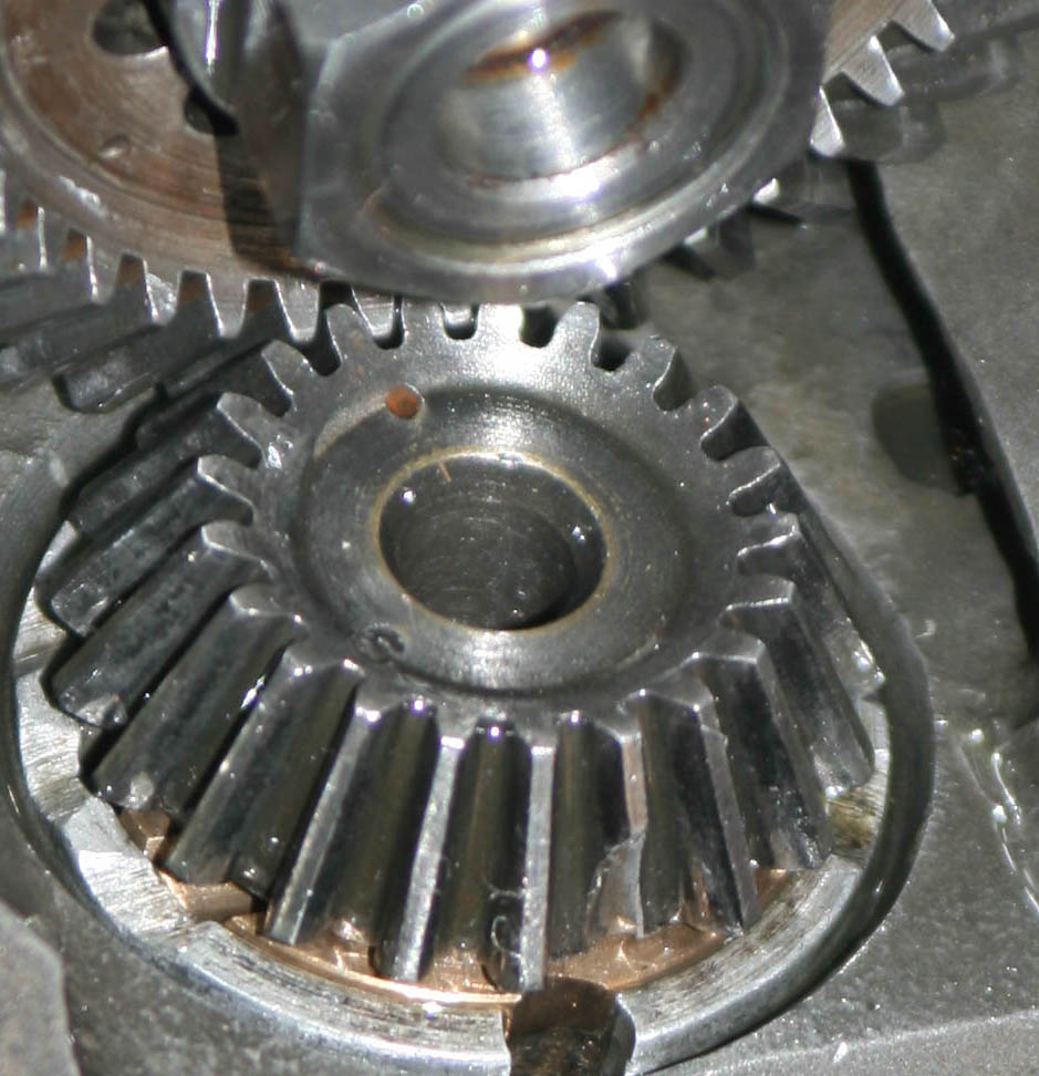
Close up of top bevel gear, showing broken tooth
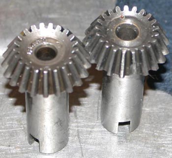
Top bevel on the left is the replacement gear I found in my very limited original bevel gear collection - a nice straight one
Search For Top Bevel
Having finally stopped cursing and resigned myself to another laborious strip down, I had to think about how to go on – as so many of you that email me regularly already know, top bevel gears are now extremely hard to find for just this reason. So I decided that before I did any further stripping down, I first ought to commence the hunt for a top bevel. Now over the years I have accumulated a small stockpile of cambox’s and top bevel housings. With these I also have some spare top bevel gears, but most of these are already reserved for future engines and I really did not want to rob a cambox of one of these gears and leave a future engine short. I spent just over two hours going through every box and cupboard, accounting for every top bevel until eventually I came to the last tin at the back of my deepest cupboard. By this time I had already confirmed how dire the situation was, having even less top bevel gears than I remember . . . not even enough to cover the number of cambox’s I had (that sounds very grand, but the reality is less impressive – the last couple of cambox housings I have are badly damaged and will need much work to reclaim), and had resigned myself to having to take one from a complete cambox. But opening this last biscuit tin, imagine my pleasant surprise when inside, as well as a number of half made bronze top bevel bushes and one original top bevel casting, I also found a very nice original top bevel vertical gear, sat in a sealable plastic bag! Looking at the contents of the tin, and the permanent marker pen marks all over the bevel housing, I then remembered this tin containing the bevel parts I used as patterns when first having vertical bevel housings cast and machined – this tin was given to the engineering company that did the machining and I must have left a top bevel in the tin for checking the bearing fits – Result!Having checked the gear over, it looked very nice and standard, with all teeth in good condition, the original Norton marks on the top face of the gear (a large percentage of the gears were made by the Coventry Die Head company), and the shaft looked unworn along its length. This last point actually presented a problem. The chipped bevel gear that was being replaced had a worn shaft when I bought it (I guess that is why it was still for sale when I bought it!). To overcome this I ground the shaft a few thou undersize to bring it back true, and then made an undersized bearing. I guessed that I would need to bore the bearing out allow the replacement bevel gear fit, with its standard size shaft. By the time I had found the bevel gear and stripped the cambox and bevel casting it was getting late on Sunday afternoon. As suspected the new bevel gear was not going to go in without some work. I decided to have a quick go with an adjustable reamer. However with the vertical oil grooves which are part of the design of this bearing I was having to take very small increments as anything larger was causing the reamer to snatch and lock the reamer in the housing. At that, I decided enough was enough and it was the end of a long day – the bearing would need boring and I was not going to be able to set that up quickly. A quick call to Rob at this point (he of crankcase jig boring fame!) and Rob very kindly agreed to take the job on in the week, while I was away in London doing my day job, ready for the next weekend so as not to hold up the build. True to his word, Rob texted me Thursday night in my hotel room in London to tell me the job was ready and Friday night when back in Leicester I picked it up. Rob had done his normal excellent job and the bevel gear was a nice slide fit in the bearing. Rob had also taken the effort to make a jig for holding the casting, should it be useful for us again in the future.
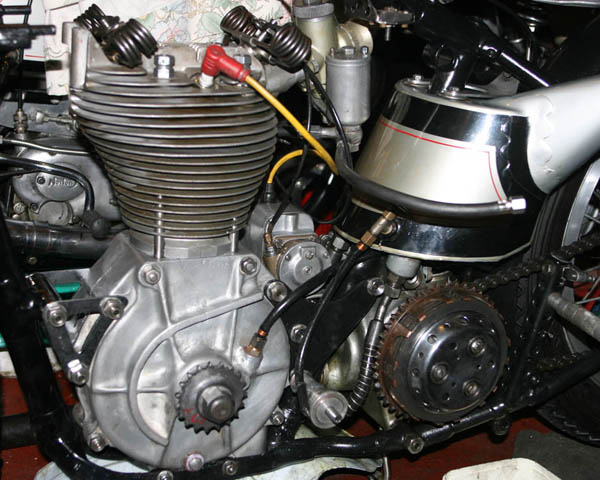
Here is the Norton with engine back in the frame, just about to do the cambox reassembly. Notice crankcase welding - while not totally invisible is certainly not that obvious
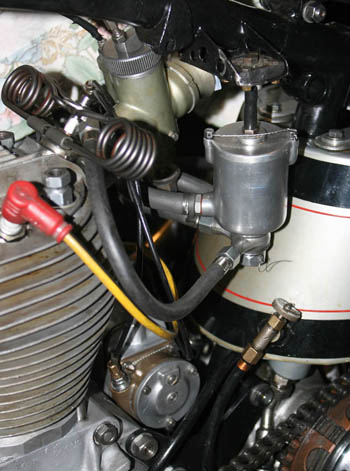
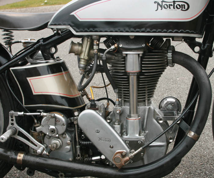
Last task was to fit the 'big bore' remote float chamber I picked up from Ian Bain at Cadwell. Although very similar in appearence to the original Amal remote I sometimes fit, this one has different interals and can pass very large quanties - ideal for methanol
And Final Assembly . . . Again
With the housing and bevel gear back in the workshop, just before re-assembling the cambox I had a last ‘feel’ of the fit of the bevel gear in the housing. Although almost perfect for a freshly built road engine, I decided it could do with just a very light final ream (virtually a hone) to allow the bearing to spin more freely – as it was going in my race engine. I do not profess to be any great shakes as a tuner, but I think it would be fair to say that this is what I take to be the definition of ‘blueprinting’ an engine – individually examining each moving part and trying to reduce friction. With plain bearings it is often a fine line between opening up a tolerance to ensure it spins freely, and not allowing excess play to develop, which can be very detrimental in a high load application such as the bevel gears. In this case, just a very light ream with plenty of cutting oil applied did the job just right – no discernible side play, but the bevel gear just span fractionally more freely – very satisfying.Incidentally, I mentioned the term ‘almost a hone’ in the previous paragraph. Those of you that look at our Online Catalog might have noticed that I own a Delapena honing machine, so why did I not hone the bearing? Well, apart from the fact that the machine was not setup for that bore – I do not actually feel comfortable about honing a phosper bronze (plain) bearing. I remember being told as a youngster that you had to be careful about some bronze bearing materials ‘picking up’, particularly abrasive materials like a honing stone – where they could then drastically reduce the life of the bevel gear shaft. Perhaps someone with more formal engineering background than I would like to confirm if I am talking rubbish or not?!
With the new top bevel gear now running lovely and free in its housing, I re-shimmed the bevel housing to get the correct level of mesh and (imperceptible) backlash in relation to the camshaft bevel gear, and then it was just a case of bevel housing/cambox re-assembly (with lashings of Castrol R and fresh gasket goo) before calling it a night (yes, still Friday night!), happy that I could pickup on final engine assembly (again!) in the morning .
Next day was not fully problem free but ended up working out ok. First job was to spend a couple of hours resetting the lower bevel gear to get the valve timing correct. You do not actually need to totally remove the lower bevel housing to do this. If you are careful you can just loosen off the four retaining nuts and lift the bevel gear housing while applying gentle pressure to the oldham coupling inside (gripping the coupling with a good pair of pliars, until you feel the bevel gear move round, as it lifts above the crankshaft bevel. Then tighten down the bevel housing again and resemble cambox etc. Having done this and played around a bit, I finally got the valve timing correct. Final job of engine assembly was to reset tappets to correct clearences for running (valve timing is done with 4 thou, but bigger tolerences when running the engine), at last job done!
I then re-timed the magneto - you may be surprised to know I do not have any fancy gizmo's to do this - I still use a dial gauge and fag paper in the points - I still have not found a better way of doing this and it is not too difficult.
New Remote Float Chamber
Final task before putting back all the peripheral bits was to fit the new remote floatchamber I had picked up from Ian Bain at Cadwell. Earlier in the year Ian had been very helpful as I was having overheating issues and we had diagnosed the carb was not getting enough methanol through. This turned out to be mainly the needle - and I have since fitted a special TT dope needle. But at the same time I measured flow of various floatchambers. Ian had told me he had made small batch's of floatchambers, that although looking like the first Amal remote floatchamber on the outside, inside they used a much later concentric style float and would pass a much greater quantity of methanol. I had picked up the floatchamber at Cadwell and it was a lovely looking piece of kit. Before fitting it I placed it vertical on the workbench with the lid off and pipes fitted, and then filled with methanol, so I could find the fuel cutoff level. I then marked off the same point on the outside of the floatchamber and made a score mark, which I was then able to use to set the floatchamber to the right height in relation to the TT carb. Finally, with new big bore black pipe connecting the float to the carb it looked a very nice piece of kit and I was able to get the setting just right - so it did not flood and methanol would come out of the TT carb when I just leaned the bike over to the right.
Back On The Road
Since putting the bike back together two weeks ago, I have now got the bike back on the road, having taken it for an MOT and already having it insured fully comprehensive. I know it may seem strange being able to MOT and tax a racing bike, but actually all you need to be legal is for it to be fitted with a bulb horn, tax disc, rear number plate and rear reflector. As well as allowing me to be able to test out the new Rocker Pads, it will also allow me to confirm if the welding will hold up and the run the engine in - as it has new main bearings and Big End fitted. Also it will give me a chance to play with the carburation and get this right - the needle was set too high for Cadwell and it was not opening up cleanly.Since getting it put together two weeks ago, the weather has been filthy. However, this did not stop me doing two runs on the bike last weekend, totalling approximately 60 miles in distance. So far I have been pleasantly surprised and the welding looks to be holding up and the engine feels quite sweet - even the carburation does not feel too far off.
I have to say though, there are better ways to spend your time than this - the second run was made in absolutely torrential rain and I was totally drenched and freezing. I was wearing an open face Davida helmet as well, and it felt like my face had been bead blasted - the worst weather I have rode in for years, with the local country roads in flood by the time I got back and the raindrops bouncing off the tarmac - bloody horrible!. I am happy to report though, that even though I lost the rear number plate somewhere along the way, as well as an engine bolt I forgot to tighten (big single cylinder vibration can often do this!), the old Norton took it all in its stride - in fact better than me, and was still running sweet as I pulled up outside my house looking like a drowned rat!
I have now fitted a new number plate and a couple of lost bolts today (Saturday 23/3), so although it is snowing outside again (Gawd!!), I hope to put some more miles on it in the next week.
Footnote: As I publish this article I have now done a further run out (with the remnants of snow still on the ground), and bike is still running well, and staying very oilt tight (amazingly). I will probably take the tank off now to check rocker pads and lift the carburettor needle one notch - I will let you know how it gets on.
By the way, does anyone have a 'Solo' electric roller starter, for starting race bikes on the back wheel? I am sick of trying to push bike a race bike in the road with cold Castor oil, if anyone has one for sale I would be interested - email me at paul.norman@racingvincent.co.uk , thanks.
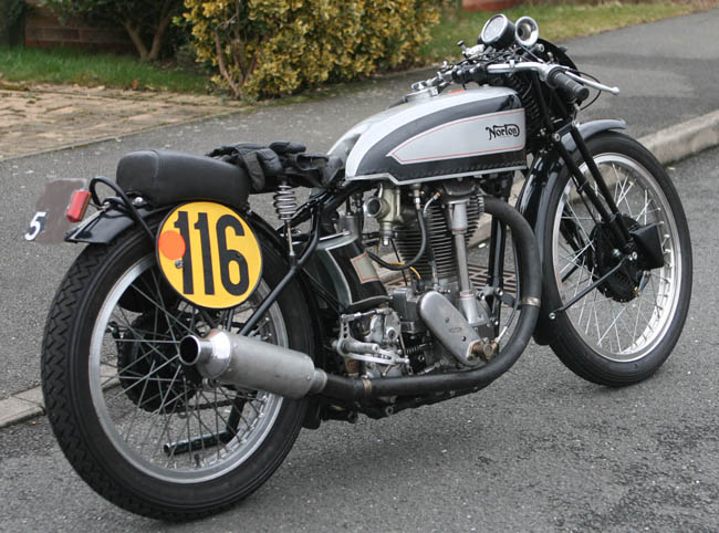 Back together again, and with the barest of road legal bits on it, I photographed the Norton here just before its first run with rebuilt engine. Notice the rear number plate and reflector (reg number hidden as always . . . too many unsavory people on the web)
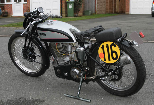
. . . and drive side of Norton. If you look closely you can just see the bulb horn in front of the rev clock, and the tax disc in the front of the engine. No stand is fitted, so I had to take the paddock stand in a backpack, along with a large padlock, in case it breaks down . . . or runs out of methanol!
This photo was taken after the third ride on the road and just over a 100 miles covered since the build completed. Riding conditions not ideal - with snow and mush patch's on the back roads, even at the end of March, that is the UK Spring for you!
Amazingly though, other than me having just given the bike a light spray with duck oil to remove the road muck from the front of the frame tube etc - this is how the engine looked after its 30 mile ride, pretty much oil tight. Note the yellowing oil tank, showing the results of a few years of castor oil throwback!